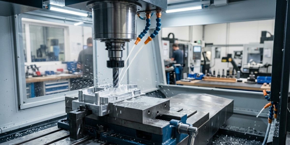

Tool chatter and vibration are common challenges in CNC machining and can have a significant impact on productivity, tool life, surface finish, and dimensional accuracy. When a cutting tool vibrates excessively during machining, it can leave unwanted marks on the workpiece, increase cutting-edge wear, generate excessive noise, and sometimes result in tool breakage. Understanding the causes of chatter and applying the right tooling and machining practices can help manufacturers achieve more stable and consistent results.
For CNC workshops and industrial manufacturers, controlling vibration starts with selecting appropriate industrial cutting tools, carbide cutting tools, CNC machining tools, CNC tool holders, and machining accessories . Khokhawala Trading LLC, an experienced Industrial Tools Supplier in Dubai , provides industrial tooling solutions for manufacturing, engineering, CNC machining, fabrication, and maintenance applications.
What Is Tool Chatter in CNC Machining?
Tool chatter is an unwanted vibration that occurs between the cutting tool, workpiece, machine, and tooling system during machining. Unlike normal cutting forces, chatter is generally unstable and can become progressively worse if the underlying cause is not corrected.
Chatter can occur during:
Milling
Turning
Drilling
Boring
Threading
Slotting
Profiling
High-speed machining
The vibration may appear as visible marks on the machined surface or as a loud, repetitive cutting sound.
Why Chatter Is a Problem
Chatter is more than a noise issue. It can directly affect machining performance and production costs.
Poor Surface Finish
Vibration causes the cutting edge to move unpredictably against the workpiece. This can leave repetitive patterns, waves, or rough areas on the finished surface.
Reduced Tool Life
Continuous vibration places additional mechanical stress on the cutting edge. This can accelerate flank wear, edge chipping, and premature tool failure.
Dimensional Inaccuracy
Tool movement caused by vibration can affect the actual cutting path. This is particularly problematic when machining tight tolerances.
Tool Breakage
Severe chatter can cause carbide tools and other cutting tools to chip or fracture.
Machine Damage
Persistent vibration can transmit forces into the spindle, tool holder, and machine structure. Over time, excessive vibration may contribute to premature wear of machine components.
Reduced Productivity
Operators may need to reduce cutting speed and feed rates to control chatter, which can reduce production efficiency.
Common Causes of Tool Chatter
Chatter can have several causes, and identifying the correct one is important before changing cutting parameters.
Common causes include:
Excessive tool overhang
Weak workholding
Incorrect cutting parameters
Excessive depth of cut
Excessive radial engagement
High tool runout
Worn cutting tools
Incorrect tool geometry
Poor-quality tool holders
Machine instability
Improper spindle speed
Flexible workpieces
Inadequate support
Poor chip evacuation
A systematic approach is often more effective than making random adjustments.
1. Minimize Tool Overhang
One of the most effective ways to reduce tool vibration is to minimize tool overhang.
A tool with excessive extension behaves like a flexible beam. As cutting forces act on it, the tool can deflect and vibrate.
Whenever possible:
Keep the tool projection as short as practical.
Avoid unnecessary extensions.
Select a holder suitable for the tool length.
Use rigid tooling for heavy cuts.
Choose specialized extended-reach tooling only when necessary.
This is particularly important when machining deep cavities or narrow features.
2. Use the Right CNC Tool Holder
The tool holder creates the connection between the machine spindle and cutting tool. Poor-quality, damaged, contaminated, or incorrectly selected holders can contribute to runout and vibration.
Common CNC tool holders include:
Collet chucks
Hydraulic holders
Shrink-fit holders
Milling chucks
Weldon holders
Shell mill holders
The appropriate holder depends on the tool, operation, machine, speed, and accuracy requirements.
For high-speed machining, holder balance and runout become particularly important.
3. Control Tool Runout
Runout occurs when a rotating tool does not remain perfectly centered around the spindle axis.
Excessive runout can cause one cutting edge to remove more material than the others. This creates uneven cutting forces and can lead to vibration.
Before machining, inspect:
Tool holder taper
Collet condition
Tool shank
Tool seating
Holder cleanliness
Tool runout
For precision applications, suitable measurement equipment should be used to verify the tool assembly.
4. Select the Correct Cutting Tool Geometry
Tool geometry has a major effect on cutting forces and vibration.
Important geometric features include:
Rake angle
Clearance angle
Helix angle
Number of flutes
Cutting-edge preparation
Nose radius
Flute design
The geometry should be selected according to the workpiece material and machining operation.
For example, tools designed for aluminum may use sharp cutting edges and flute designs optimized for chip evacuation, while tooling for harder materials may require stronger cutting edges.
Using the wrong geometry can increase cutting forces and make chatter more likely.
5. Optimize Spindle Speed
Spindle speed is one of the most important variables when controlling chatter.
Simply increasing or decreasing speed can sometimes move the machining operation away from an unstable vibration condition.
If chatter occurs, try controlled adjustments to spindle speed while monitoring:
Surface finish
Cutting sound
Spindle load
Tool wear
Machine vibration
Changes should be made within the cutting tool and machine manufacturer's recommended operating ranges.
6. Optimize Feed Rate
Feed rate also affects cutting forces and chip thickness.
An excessively high feed can overload the cutting edge, while an excessively low feed may cause rubbing instead of efficient cutting.
The correct feed should consider:
Tool diameter
Number of flutes
Workpiece material
Cutting speed
Radial engagement
Axial depth of cut
Machine rigidity
A balanced feed rate can help maintain stable cutting without unnecessarily increasing tool load.
7. Reduce Depth of Cut When Necessary
Deep cuts increase the amount of material being removed and therefore increase cutting forces.
If chatter occurs during heavy roughing, reducing axial depth of cut may help stabilize the process.
However, reducing depth of cut is not always the only solution. In some milling applications, reducing radial engagement while maintaining an appropriate axial depth can provide better productivity and lower cutting forces.
The correct approach depends on the toolpath and machine capability.
8. Improve Workholding Rigidity
A stable tool cannot compensate for an unstable workpiece.
If the workpiece moves or vibrates during machining, the resulting cutting conditions can become unpredictable.
Proper workholding may include:
CNC vises
Chucks
Collet systems
Hydraulic fixtures
Pneumatic fixtures
Soft jaws
Custom fixtures
Modular workholding systems
The workpiece should be supported as close as practical to the cutting zone.
Thin components may require additional support to prevent deflection.
9. Select the Right Tool Diameter
Tool diameter influences rigidity.
Larger-diameter tools generally have greater resistance to bending than smaller tools of similar length.
However, the largest tool is not always the best option. Tool diameter should be selected according to:
Feature size
Corner radius
Pocket geometry
Required surface finish
Machine capacity
Material removal requirements
Using a suitable diameter can help balance accessibility and rigidity.
10. Use Appropriate Cutting Tool Material
Carbide cutting tools are widely used in CNC machining because of their hardness, wear resistance, and ability to operate at relatively high cutting speeds.
The correct grade and geometry are still important. A tool should be selected according to the workpiece material and application.
In some situations, a tougher grade may be preferable where interrupted cuts or vibration are present.
The goal is to match tool strength and cutting performance to actual machining conditions.
11. Maintain Proper Spindle and Machine Condition
Machine condition can also contribute to vibration.
Potential issues include:
Spindle runout
Damaged spindle taper
Worn bearings
Poor machine alignment
Loose machine components
Improper leveling
Damaged tool holders
Regular machine maintenance can help identify mechanical problems before they affect production quality.
Spindle maintenance is particularly important for high-speed CNC operations.
12. Improve Chip Evacuation
Poor chip evacuation can create unstable cutting conditions.
Accumulated chips may be recut, trapped in pockets, or interfere with the cutting edge. This can increase cutting forces and heat.
Appropriate coolant, air blast, through-tool coolant, or optimized toolpath strategies can improve chip evacuation.
The best method depends on the workpiece material, operation, tool geometry, and machine configuration.
13. Choose the Right Milling Strategy
Toolpath selection can have a major impact on cutting stability.
Traditional full-width slotting can create high cutting loads because the tool remains heavily engaged with the material.
Depending on the application, strategies such as adaptive or high-efficiency milling can reduce radial engagement and maintain more consistent cutting conditions.
Other strategies include:
Trochoidal milling
Constant-engagement toolpaths
Dynamic milling
Optimized contouring
Appropriate entry and exit movements
The objective is to maintain stable tool engagement and avoid sudden changes in cutting load.
Chatter During Turning Operations
Chatter is not limited to milling.
During CNC turning, vibration can result from:
Excessive tool overhang
Long workpiece projection
Weak workholding
Incorrect insert geometry
Excessive depth of cut
Poor machine rigidity
Incorrect spindle speed
Using a rigid turning tool holder, reducing unsupported workpiece length, and selecting suitable insert geometry can help stabilize turning operations.
For long boring applications, anti-vibration or damped boring solutions may also be considered where appropriate.
How to Diagnose Chatter Step by Step
When chatter occurs, avoid changing everything at once.
Use a systematic process:
Step 1: Inspect the Tool
Check for wear, chipping, damage, or incorrect installation.
Step 2: Check Tool Overhang
Reduce projection if possible.
Step 3: Check the Holder
Inspect the taper, collet, nut, and holder for contamination or damage.
Step 4: Check Workholding
Verify that the workpiece is securely supported.
Step 5: Review Cutting Parameters
Check spindle speed, feed, depth of cut, and radial engagement.
Step 6: Check Machine Condition
Investigate spindle runout, machine rigidity, and possible mechanical problems.
Step 7: Test Controlled Changes
Change one parameter at a time and evaluate the result.
This approach makes it easier to identify the actual cause.
Common Mistakes That Increase CNC Chatter
Several practices can unintentionally make vibration worse:
Using excessively long tools
Ignoring tool runout
Using worn inserts or cutting edges
Selecting the wrong tool geometry
Overloading the tool with excessive depth of cut
Using weak workholding
Ignoring spindle condition
Operating outside recommended tool parameters
Allowing chips to accumulate
Using damaged tool holders
Changing multiple cutting parameters without monitoring the results
Avoiding these mistakes can significantly improve machining stability.
Best Practices for Preventing Tool Chatter
A reliable CNC machining process should include the following practices:
Keep tool overhang as short as practical.
Select rigid and suitable CNC tool holders.
Maintain low tool runout.
Match tool geometry to the workpiece material.
Optimize spindle speed and feed rate.
Control axial and radial cutting engagement.
Use stable workholding.
Select an appropriate tool diameter.
Monitor cutting tool wear.
Maintain the CNC spindle and machine.
Improve chip evacuation.
Use appropriate coolant or lubrication.
Choose stable toolpaths for high material removal.
Verify finished components with precision measuring tools.
Benefits of Controlling Chatter and Vibration
Effective vibration control can provide significant benefits:
Better surface finish
Longer cutting tool life
Improved dimensional accuracy
Reduced tool breakage
Lower machining noise
More consistent production
Reduced scrap and rework
Better machine reliability
Improved productivity
More predictable machining performance
These improvements can be particularly valuable in precision manufacturing and high-volume CNC production.
Conclusion
Preventing tool chatter and vibration during CNC machining requires attention to the entire machining system. Tool geometry, holder selection, runout, tool overhang, cutting parameters, workholding, machine condition, and chip evacuation all influence machining stability.
By appropriate selecting industrial cutting tools, carbide cutting tools, CNC machining tools, CNC tool holders, and machining accessories , manufacturers can reduce unnecessary vibration and improve machining accuracy and productivity. Precision measuring tools can also help verify runout, dimensions, and finished component quality.
Khokhawala Trading LLC supports manufacturing, engineering, CNC, and industrial businesses with dependable tooling solutions for a wide range of applications. As an experienced Industrial Tools Supplier in Dubai , the company provides access to industrial tooling and machining solutions designed to support accurate, stable, and productive machining operations.